Accumulator: Difference between revisions
m wording |
Chumfactor (talk | contribs) m Clarify pole disconnection change in 2.0 |
||
| Line 22: | Line 22: | ||
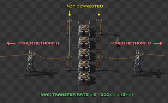
[[File:Accumulator_Network_Isolation.png|thumb|left|550px|Example of accumulators sharing two separate networks. ''(Click to enlarge)'']] | [[File:Accumulator_Network_Isolation.png|thumb|left|550px|Example of accumulators sharing two separate networks. ''(Click to enlarge)'']] | ||
{{clear}} | {{clear}} | ||
The two power networks A and B are not directly connected to each other: They are connected only through the accumulators, which are shared by both networks. This is accomplished by setting up electric poles for each network connected to the accumulators, then ensuring the sets of poles are not connected to each other (which can be done by crafting a copper wire then dragging it between two connected poles to sever the connection, exactly as is done for disconnecting circuit wires). | The two power networks A and B are not directly connected to each other: They are connected only through the accumulators, which are shared by both networks. This is accomplished by setting up electric poles for each network connected to the accumulators, then ensuring the sets of poles are not connected to each other (which can be done by crafting a copper wire then dragging it between two connected poles to sever the connection, exactly as is done for disconnecting circuit wires). (As of 2.0, rather than crafted copper wire, the Make Copper Wire create tool in the UI -- near the Red & Green circuit wires -- is used.) | ||
In the above example: | In the above example: | ||
Revision as of 16:36, 7 December 2024
| Accumulator |
- Base game
- Space Age mod
|
Recipe |
|||||||||||||
| ++ → | |||||||||||||
|
Total raw |
|||||||||||||
| ++ | |||||||||||||
|
Map color |
|||||||||||||
|
Health |
|
||||||||||||
|
Stack size |
50 |
||||||||||||
|
50 (1 stack) |
|||||||||||||
|
Dimensions |
2×2 |
||||||||||||
|
Energy capacity |
|
||||||||||||
|
Power input |
|
||||||||||||
|
Power output |
|
||||||||||||
|
Mining time |
0.1 |
||||||||||||
|
Prototype type |
|||||||||||||
|
Internal name |
accumulator |
||||||||||||
|
Required technologies |
|||||||||||||
|
Produced by |
|||||||||||||
|
Consumed by |
|||||||||||||
Object description
The Accumulator stores a limited amount of energy when available production exceeds demand, and releases it in the opposite case. The accumulator can store up to 5 MJ of energy. Its maximum charge/discharge rate is 300 kW. If connected to a circuit network, an accumulator will output its level of charge, as an integer from 0 to 100, to a specified signal.
Notes
- 5MJ of stored energy takes approximately 17s to fully charge/discharge at the maximum rate of 300kW. Read Time#Seconds for further time related calculations.
- It takes 20 accumulators (100MJ) to maintain 1MW through the night, because the accumulators don't immediately start discharging at the beginning of dusk, see the graph in this post.
- For balanced solar power, every 21 accumulators need to have 25 solar panels supporting them (at 50kW per accumulator)
- When discharged above maximum speed by multiple unconnected poles, energy will not be distributed equally (some loads may get 100% demand, others 0%)
- May be used to provide a limited amount of power (multiples of maximum charge rate) to a section of the grid.
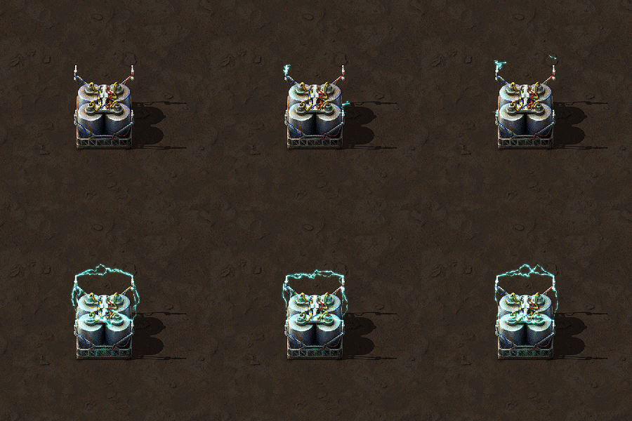
- Produces light when charging and discharging.
- Can act as an emergency backup for the factory in case of blackout, until main power supply is restored.
- Can be used to power the base at night if it relies heavily on solar panels.
- Can act to satisfy surging demands of certain loads. If the power usage of one device exceeds production for a few seconds or so, the accumulator can provide power to the grid until said device shuts down or requires a lesser power requirement.
Other uses
Note that if throughput should not be limited, a power switch can be used instead.
Isolation of Power Networks
Accumulators can be used to isolate two separate power networks, which has a number of uses. Since accumulators have a lower delivery priority than any other entity, this guarantees that they only receive energy when you have enough left over after powering all other entities in a network. At the same time, accumulators can also be used to deliver energy in another electrical network, and can charge and discharge at the same time. Consider the following example:

The two power networks A and B are not directly connected to each other: They are connected only through the accumulators, which are shared by both networks. This is accomplished by setting up electric poles for each network connected to the accumulators, then ensuring the sets of poles are not connected to each other (which can be done by crafting a copper wire then dragging it between two connected poles to sever the connection, exactly as is done for disconnecting circuit wires). (As of 2.0, rather than crafted copper wire, the Make Copper Wire create tool in the UI -- near the Red & Green circuit wires -- is used.)
In the above example:
- The accumulators will only charge if extra power is being produced by network A or B.
- The accumulators will discharge as needed into either network if one is not producing enough power.
- Since the maximum input/output rate of an accumulator is 300 kW, power flow between the two networks will be limited to 300 kW times the number of accumulators (1.5 MW in the example).
- Note that this isolation is bidirectional: Either network can charge the accumulators, and the accumulators can discharge into either network.
This technique can be used whenever this type of isolation is desired.
Reduction of Energy Consumption in Critical Situations
In particular, one good use for the above technique is to limit electricity consumption in low power situations by isolating non-critical parts of your factory (such as Radar, Labs, Electric furnaces, electric miners, Beacons, etc.) from critical parts (such as lasers, ammo production, or whatever your priorities are).
To do this, place your main generators and critical components on one network and place your non-critical components on another network, isolating the two as above. Now, two things will happen:
- Power will only flow to the non-critical network when you are generating a surplus on the main network, and
- The rate will always be limited to 300 kW per accumulator.
Because the accumulators will only receive power if you have a surplus on the main network, this will in effect deactivate the low-priority network when electricity is in short supply. This will also limit power consumption of the low priority network if its usage becomes high, for example if you have two factories on a low priority network and usually only one of them runs at a time, if both happen to run they won't consume more than the total limit, they'll just slow down.
Essentially you are saying "only deliver power to these systems if I have enough to spare, and even then don't exceed this delivery rate".
In general this is a technique which works well when you've just researched accumulators and solar panels, but don't have enough resources to build big solar farms and accumulator farms yet.
History
- 0.13.3:
- Reduced collision box of big electric pole to allow squeezing between it and an accumulator.
- 0.13.0:
- Now connectible to the circuit network.
- 0.12.0:
- Heavy optimisations by merging them into groups.
- 0.11.0:
- Drastically slowed crafting to 10 secs.
- 0.7.1:
- Capacity doubled, increase I/O to 300 watts.
- 0.4.1:
- Added charging animation.
- 0.4.0:
- Introduced
