Electric system

The Electric system is used to power a lot of different machines; the game can hardly be played without using electricity. Every machine has its own internal electric capacity. When energy is produced, it is evenly distributed to all machines in the network that need electricity. Electricity is one of two ways machines can be powered, the other being burner devices running off of fuel.
Network mechanics
Generators
There are several ways to produce electricity. More details about each method are available on the power production page.
- Steam engines – Most common, requires boilers (which consume water and fuel).
- Solar panels – Free energy, but only works during daylight. Usually used with accumulators.
- Accumulators – Energy storage, see below
- Steam turbines – High-power steam engines. Used to generate power from a nuclear reactor, acid neutralisation
 , or heating towers
 .
. - Lightning rods
 & lightning collectors
 - Converts lightning strikes during Fulgora's
 night into power.
 - Fusion generators
 - Converts plasma from a fusion reactor into electricity.
If a network consumes less power than is produced, its steam engines, turbines, and fusion generators will slow down so that no power is wasted.
Storage

Energy can be stored in:
- Fuel. It can be burnt to generate power.
- Accumulators. Accumulators charge using excess power generated, and discharge when demand exceeds normal production.
- Steam. It can be created in boilers or heat exchangers and stored in the storage tank, allowing steam engines or steam turbines to operate on-demand.
- Heat pipes. Heat pipes can buffer up to 500MJ of energy across their working range of 500°C to 1000°C, although in practice this will be less depending on distance due to the way heat transfer works.
Steam tanks as power storage
A storage tank filled with heat exchanger 500°C steam stores around 2.4GJ; a storage tank filled with boiler 165°C Steam stores 750MJ.
There are several advantages to storing energy in storage tanks compared with storing it in an accumulator:
- The energy density of a storage tank tile is much higher than it is with accumulators.
- For 165°C steam (produced with boilers), a single storage tank stores as much as 150 accumulators:
750MJ / 5MJ = 150 - For 500°C steam (produced using heat exchangers), a single storage tank stores as much as 480 accumulators:
2400MJ / 5MJ = 480
- For 165°C steam (produced with boilers), a single storage tank stores as much as 150 accumulators:
- A nuclear reactor always fully burns a fuel cell, releasing 8GJ (or more with the multiple reactor bonus) even if power demand is lower. The excess energy can be stored as steam.
- A single accumulator's maximum discharge rate is 300kW. On a very heavy load (e.g. laser turret firing), a small accumulator array may not discharge fast enough, causing power disruptions. A steam engine can produce 900kW of energy from the stored steam (3 times faster discharge rate), and a turbine can produce 5800kW (6.4 times faster discharge rate). In other words, a number of turbines or steam engines with steam storage can cope with much higher bursts than the same number of accumulators.
- Steam can be transferred via trains and then consumed remotely via turbines or steam engines. This essentially "transports electricity" using trains.
Energy storage density comparison
| Storage | Capacity | Accumulators | Size | Density (MJ/tile) |
|---|---|---|---|---|
| Accumulator | 5MJ | 1 | 2x2 | 1.25 |
| Steam tank (165°C) | 750MJ | 150 | 3x3 | 83.33 |
| Steam tank (500°C) | 2400MJ | 480 | 3x3 | 266.66 |
| Heat pipe | 500MJ1 | 100 | 1x1 | 5001 |
(1) Theoretical maximum, actual capacity depends on distance due to heat transfer mechanics.
Distribution
Power poles are used to transmit energy. There are 4 types of power pole, each having differently configured properties. The properties are coverage area (area in which machines are placed to be affected by the pole) and wire reach (the distance across which a pole can connect with another pole). If two poles of different wire reach are to be connected, the smallest of either applies.
- Small electric pole – Second smallest coverage area, shortest cable length, available without research.
- Medium electric pole – Second largest coverage area, average cable length.
- Big electric pole – Smallest coverage area, longest cable length.
- Substation – Largest coverage area, second longest cable length, but most expensive to build.
Consumption

The majority of machines in Factorio consume electricity. There are two aspects to a machine's energy use.
- Energy consumption – The energy consumed by the machine while it is actively carrying out a process (crafting an item, moving an item, etc). If an electric network does not have enough power generation to supply all the machines in it, the electricity will be evenly spread across all machines in the network (based on each machine's demand), and all machines will slow down proportionally to the power available.
- For example: If an assembling machine 3 (210kW) and an electric mining drill (90kW) are on a network (90+210 = 300kW), but the network only has 3 solar panels (3×60kW = 180kW) to power them, the Assembling machine and Mining drill will both run at 60% speed (180/300=0.6).
- Drain – The energy consumed by the machine whether it is active or not. Most machines consume a small amount of power just being connected to a network. This is usually negligible, but can become notable in small factories where power is limited. Drain is cumulative with energy cosumption - for example, an active assembling machine 2 will consume 155 kW (150kW energy consumption + 5kW drain).
Connection

A network is created by placing electrical generators (such as steam engines or solar panels) and electrical consumers, then ensuring a connection between the generator and consumer can be made using Distributors (such as small electric poles) that are connected together. Electric poles cover differently sized areas depending on their type. The area of coverage appears as a blue overlay around the pole. If two poles are placed close enough, the poles connect automatically. A building is connected if one tile of the building is in a covered area. Hovering the cursor over a pole reports the current satisfaction of power demands in that pole's network, and clicking on a pole will provide a detailed GUI about that pole's electric network. (See below)
- Use shift-click on a existing pole to remove all its connections to other poles.
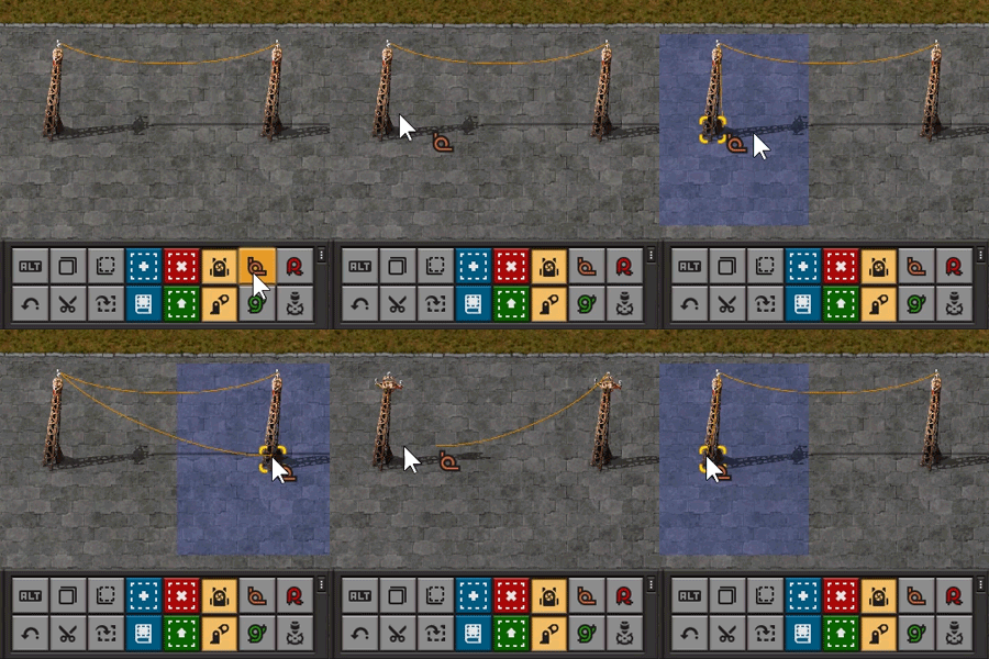
- Unconnected poles can be connected with copper wire tool in the shortcut bar by dragging from pole to pole (Left click on the bottom of the pole while the tool is activated.)
- Individual connections can be removed by "connecting" them with copper wire tool. This will not consume anything.
- You can use place-key (default left mouse) while running/driving to auto-place poles at their greatest connectible distance while covering all unpowered entities on the way. This allows for complete efficiency when connecting long distances. If connecting over long distances, using big electric poles is recommended.
A newly-placed electric pole will be automatically connected to nearby poles according to the following rules:
- It will be connected to other available poles, starting with the closest one.
- It won't be connected to 2 poles connected to each other (it won't form a 3 pole triangle).
- It will not be connected to more than 5 other poles.
Electric network info screen


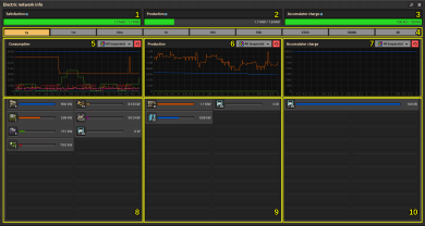
The Electric network info GUI can be accessed by left-clicking any electric pole nearby.
You can see only the info from the electric network to which that pole is connected! Unlike the production-info (press P) the electric network info is not measured globally, but by network.
- Satisfaction – The current amount of energy consumed by the network. This bar should be full. If it is not full, it means that the machines connected to the network are consuming more power than is produced, and the bar will change color to yellow (>50%) or red (<50%).
- Production – The current energy produced by the network. This bar should never be full. If it is full, it means that the machines connected to the network are consuming all available energy. The less full this bar is, the more surplus energy is available.
- Accumulator charge – How much energy is currently held inside of the accumulators connected to your network. Measured in joules; 1 Joule = 1 Watt * 1 second (see also wikipedia:Joule). This bar should be able to fill fully before emptying again.
- Timespan - Set the time span for the graphs below. "5s" means over the last 5 seconds.
- Consumption Graph – Shows the consumption of the different parts of the network over time.
- Production Graph – Shows the production of the different producers of the network over time.
- Accumulator Graph – Shows the energy held by the accumulators in the network over time.
- Detailed Consumption – A list of consumers from highest power consumption to lowest. In the picture example, 3 radars consume the most power, at 900kW.
- Detailed Production – A list of producers from highest power production to lowest. In the picture example, 8 steam engines produce the most electricity in the factory.
- Detailed Accumulator – A list of energy storage status of the accumulators. In the picture example, 100MJ energy is held in 20 accumulators.
Note that the timeframe influences the shown detailed production/consumption: the displayed watts is the total average power production or consumption over the full time. Setting longer timeframes also allows seeing the past production or consumption of machines even if they are not currently connected to the network.
In Space age expansion, filters are provided for graphs to shows the stats for the structures of the selected quality tiers.
Network priorities
Electricity is provided on a priority basis. The demand for energy is satisfied by generators in following order:
- Solar panels – Top priority; they always work at maximum performance available, unless they can cover all demand of the network, in which case they match demand.
- Lightning rods/collectors
 - It is unclear if rods/collectors have equal priority to panels or just below them, but if they have lower priority, their priority is still higher than those below.
 - Steam engines, steam turbines, and fusion generators
 – They match whatever demand solar panels cannot satisfy. Note that all of these have the same priority; leftover demand is equally divided among both.
 - Accumulator – Last resort. They are only discharged when demand cannot be met by other means. They are also only charged when all demand is met, and there is yet more power available.
There may be situations where different behavior is desired (such as solar panels combined with accumulators for night-and-day delivery), in which case clever use of a power switch and the circuit network is in order.