Tutorial:Circuit network cookbook: Difference between revisions
Jump to navigation
Jump to search
(some lil formatting edits) |
m (Remove personal references, clean up page formatting/grammar) |
||
| Line 1: | Line 1: | ||
== Introduction == | == Introduction == | ||
This page provides examples of simple circuit network designs and some not so simple that others can use, combine and modify. They are designed to be as easy to understand as possible. | This page provides examples of simple circuit network designs and some not so simple designs that others can use, combine and modify. They are designed to be as easy to understand as possible. | ||
== Oil Setups == | == Oil Setups == | ||
[[File:LgtOilCracking.png|left]] | [[File:LgtOilCracking.png|left|400x400px]] | ||
=== Light Oil Cracking === | === Light Oil Cracking === | ||
*This circuit provides balanced light oil and petroleum gas production by cracking excess light oil into gas. | * This circuit provides balanced light oil and petroleum gas production by cracking excess light oil into gas. | ||
*The [[Small pump]] is connected to the [[Storage tank]] by a [[Red wire]]. | * The [[Small pump]] is connected to the [[Storage tank]] by a [[Red wire]]. | ||
*The [[small pump]] has an enabled condition set to '''Light Oil > 2000'''. | * The [[small pump]] has an enabled condition set to '''Light Oil > 2000'''. | ||
{{clear}} | {{clear}} | ||
[[File:HvyOilCracking.png|left]] | [[File:HvyOilCracking.png|left|400x400px]] | ||
=== Heavy Oil Cracking === | === Heavy Oil Cracking === | ||
*This circuit extends on the previous circuit by adding optional heavy oil cracking to provide lubricant etc. | * This circuit extends on the previous circuit by adding optional heavy oil cracking to provide lubricant etc. | ||
*The [[Small pump]] has an enabled condition set to '''Heavy oil > 2000'''. | * The [[Small pump]] has an enabled condition set to '''Heavy oil > 2000'''. | ||
{{clear}} | {{clear}} | ||
[[file:BalancedPlasticSulfur.png|left]] | [[file:BalancedPlasticSulfur.png|left|400x400px]] | ||
=== Petroleum split evenly between plastic and sulphuric acid === | === Petroleum split evenly between plastic and sulphuric acid === | ||
*This circuit buffers gas in the tank until there is at least 100, then it lets the tank drain until there is less than 50 and the cycle repeats. | * This circuit buffers gas in the tank until there is at least 100, then it lets the tank drain until there is less than 50 and the cycle repeats. | ||
*It has a few elements that work together to do achieve this. | * It has a few elements that work together to do achieve this. | ||
*Firstly the [[Small pump]] is connected to the [[Wooden chest]] by a [[Red wire]] and the enabled condition on the [[Small pump]] is set to '''Raw wood > 0'''. | * Firstly the [[Small pump]] is connected to the [[Wooden chest]] by a [[Red wire]] and the enabled condition on the [[Small pump]] is set to '''Raw wood > 0'''. | ||
*Both of the [[Basic inserter]]s are connected to the [[Storage tank]] by [[Red wire]]s. | * Both of the [[Basic inserter]]s are connected to the [[Storage tank]] by [[Red wire]]s. | ||
*The enabled condition on the left inserter is '''Petroleum gas > 100''' | * The enabled condition on the left inserter is '''Petroleum gas > 100''' | ||
*The enabled condition on the right inserter is '''Petroleum gas < 50'''. | * The enabled condition on the right inserter is '''Petroleum gas < 50'''. | ||
*You will need to insert a single "Raw wood" into the chest to make it all work. | * You will need to insert a single "Raw wood" into the chest to make it all work. | ||
<br /> | <br /> | ||
*It is also possible to do this with [[decider combinator]]s instead of the inserters, belt and the Wood chest or even just belts. | * It is also possible to do this with [[decider combinator]]s instead of the inserters, belt and the Wood chest or even just belts. | ||
{{clear}} | {{clear}} | ||
== Lights == | == Lights == | ||
[[File:ConditionalLights.png|left]] | [[File:ConditionalLights.png|left|400x400px]] | ||
=== Conditional Lights === | === Conditional Lights === | ||
*In this circuit we connect a series of [[lamp]]s to a [[Storage Tank]]. | * In this circuit we connect a series of [[lamp]]s to a [[Storage Tank]]. | ||
*By setting different conditions on each [[lamp]] we can build an indicator strip. | * By setting different conditions on each [[lamp]] we can build an indicator strip. | ||
*The Enabled condition of the first [[lamp]] is '''Petroleum gas > 100'''. | * The Enabled condition of the first [[lamp]] is '''Petroleum gas > 100'''. | ||
*The others light up when gas is greater than 200, 300, 400 | * The others light up when gas is greater than 200, 300, 400 and 500 respectively. | ||
{{clear}} | {{clear}} | ||
[[File:ColoredLights.png|left]] | [[File:ColoredLights.png|left|400x400px]] | ||
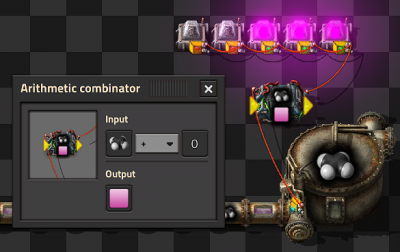
=== Colored Lights === | === Colored Lights === | ||
*To light a [[lamp]] with a color rather than white, you need to do two things. | * To light a [[lamp]] with a color rather than white, you need to do two things. | ||
*1. Send a colored signal to the lamp | * 1. Send a colored signal to the lamp | ||
*2. Select the "Use colors" | * 2. Select the "Use colors" check box on the lamp. | ||
*In this case we want to convert a Petroleum gas signal into a pink signal. | * In this case we want to convert a Petroleum gas signal into a pink signal. | ||
*We can do this with an [[Arithmetic combinator]], setting the input to Petroleum Gas + 0 (the constant 0 not the signal 0) and set the output to the Pink signal (on the bottom row of the last tab of signals.) | * We can do this with an [[Arithmetic combinator]], setting the input to Petroleum Gas + 0 (the constant 0 not the signal 0) and set the output to the Pink signal (on the bottom row of the last tab of signals.) | ||
{{clear}} | {{clear}} | ||
== Misc == | == Misc == | ||
[[file:MulitipleChestsAndPoles.png|left]] | [[file:MulitipleChestsAndPoles.png|left|400x400px]] | ||
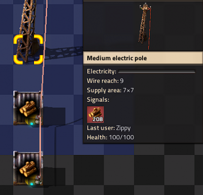
=== Multiple Storages === | === Multiple Storages === | ||
*If you connect multiple chests to a pole, the pole displays the sum of items in all the chests. | * If you connect multiple chests to a pole, the pole displays the sum of items in all the chests. | ||
*This also works with [[Storage tank]]s and [[roboport]]s. | * This also works with [[Storage tank]]s and [[roboport]]s. | ||
{{clear}} | {{clear}} | ||
[[File:ConstantComb.png|left]] | [[File:ConstantComb.png|left|400x400px]] | ||
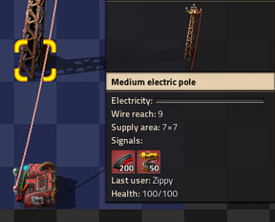
=== Constant combinator === | === Constant combinator === | ||
*With a [[constant combinator]] you can generate any signals you my need. | * With a [[constant combinator]] you can generate any signals you my need. | ||
*In this example we have generated a signal of 50 Laser turrets and 200 Piercing round magazine. | * In this example we have generated a signal of 50 Laser turrets and 200 Piercing round magazine. | ||
*Constant combinators are not of much use on their own but we shall use them later. | * Constant combinators are not of much use on their own but we shall use them later. | ||
{{clear}} | {{clear}} | ||
[[ | [[File:LogicGates.png|left|400x400px]] | ||
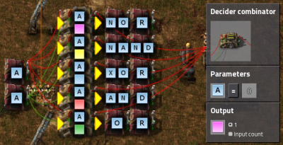
=== Logic gates === | === Logic gates === | ||
*In each case | * In each case the two inputs can be connected with the same color wire or different colors. The inputs are powered by two [[Constant combinator]]s each of them output an A signal with value 1 for true and nothing or false. | ||
*You can use [[Decider combinator]]s to make all of the common logic gates. | * You can use [[Decider combinator]]s to make all of the common logic gates. | ||
*The output for each should be set to 1 and the signal of your choice. | * The output for each should be set to 1 and the signal of your choice. | ||
*Use the following settings to create different gates | * Use the following settings to create different gates: | ||
{{clear}} | {{clear}} | ||
[[File:ThisASign.png|left]] | NOT A=0 | ||
NOR A=0 | |||
NAND A<2 | |||
XOR A=1 | |||
AND A=2 | |||
OR A>0 | |||
{{clear}} | |||
[[File:ThisASign.png|left|400x400px]] | |||
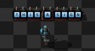
=== Constant combinator signs === | === Constant combinator signs === | ||
*You can use [[Constant combinator]]s to make signs | * You can use [[Constant combinator]]s to make signs, just set the letter signals in the combinator, each combinator can display 2 characters side by side. | ||
{{clear}} | {{clear}} | ||
[[File:MemoryCell.png|left]] | [[File:MemoryCell.png|left|400x400px]] | ||
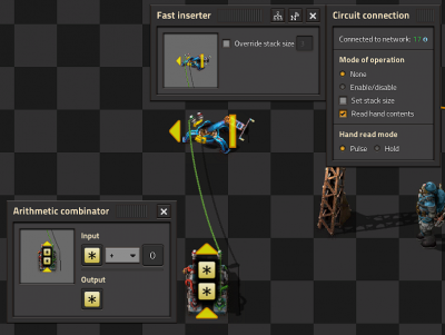
=== Memory Cell / Counter === | === Memory Cell / Counter === | ||
*Basic memory cell that counts all the items moved by the inserter | * Basic memory cell that counts all the items moved by the inserter | ||
*The [[Fast inserter]] is connected to '''BOTH''' ends of the arithmetic combinator. | * The [[Fast inserter]] is connected to '''BOTH''' ends of the arithmetic combinator. | ||
*If the [[Fast inserter]] hasn't picked anything up this tick the input to the Arithmetic combinator is the same as and output and hence the values are persisted. | * If the [[Fast inserter]] hasn't picked anything up this tick the input to the Arithmetic combinator is the same as and output and hence the values are persisted. | ||
*When the [[Fast inserter]] does pick something up its value is added to the output from the previous tick thus incrementing that item. | * When the [[Fast inserter]] does pick something up its value is added to the output from the previous tick thus incrementing that item. | ||
{{clear}} | {{clear}} | ||
== Inserters == | == Inserters == | ||
[[File:LimitItemsPlacedIntoAChest.png|left]] | [[File:LimitItemsPlacedIntoAChest.png|left|400x400px]] | ||
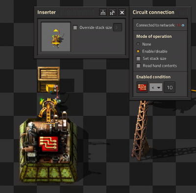
=== Limit items placed into a chest === | === Limit items placed into a chest === | ||
* The [[Basic inserter]] is connected to the [[Wooden chest]] using a [[Red wire]]. | * The [[Basic inserter]] is connected to the [[Wooden chest]] using a [[Red wire]]. | ||
* The inserter's enabled condition is '''Advanced Circuit < 10'''. | * The inserter's enabled condition is '''Advanced Circuit < 10'''. | ||
* In reality this means the inserter may place more than 10 Advanced circuits in the chest because it could pick up-to 3 at once. | * In reality this means the inserter may place more than 10 Advanced circuits in the chest because it could pick up-to 3 at once. | ||
* This effect can be even greater with Stack inserters because of their large carrying capacity. | * This effect can be even greater with Stack inserters because of their large carrying capacity. | ||
* This technique still gives far greater control than limiting the inventory on the chest. | * This technique still gives far greater control than limiting the inventory on the chest. | ||
{{clear}} | {{clear}} | ||
[[File:SmartOutpostUnloader.png|left]] | [[File:SmartOutpostUnloader.png|left|400x400px]] | ||
=== Keeping outpost stocked with specified items === | === Keeping outpost stocked with specified items === | ||
* This circuit keeps a [[Storage chest]] at an outpost stocked with | * This circuit keeps a [[Storage chest]] at an outpost stocked with customized levels of different items. | ||
* For example you could keep an outpost stocked with 50 laser turrets and 200 piercing magazine rounds but not have to worry about it being over filled. | * For example you could keep an outpost stocked with 50 laser turrets and 200 piercing magazine rounds but not have to worry about it being over filled. | ||
* The [[storage chest]] is attached to the input of the [[Arithmetic combinator]] (left side in the picture) with a [[Red wire]]. | * The [[storage chest]] is attached to the input of the [[Arithmetic combinator]] (left side in the picture) with a [[Red wire]]. | ||
* Another couple of [[Red wire]]s join the output of the [[Arithmetic combinator]] (right side) to the [[constant combinator]] and to the [[stack filter inserter]]. | * Another couple of [[Red wire]]s join the output of the [[Arithmetic combinator]] (right side) to the [[constant combinator]] and to the [[stack filter inserter]]. | ||
* The [[Arithmetic combinator]] '''multiples''' each input value (from the storage chest) by '''-1'''. | * The [[Arithmetic combinator]] '''multiples''' each input value (from the storage chest) by '''-1'''. | ||
* Finally the filter stack inserter's mode of operation is set to '''Set filters'''. | * Finally the filter stack inserter's mode of operation is set to '''Set filters'''. | ||
<br /> | <br /> | ||
* So the input to the [[stack filter inserter]] is '''<Constant combinator> - <Storage chest contents>''' and the filter is set to filter the item of greatest demand. | * So the input to the [[stack filter inserter]] is '''<Constant combinator> - <Storage chest contents>''' and the filter is set to filter the item of greatest demand. | ||
{{clear}} | {{clear}} | ||
[[File:SolarAccumalatorBalancer.png|left]] | [[File:SolarAccumalatorBalancer.png|left|400x400px]] | ||
=== Balanced Solar panel / Accumulator Production === | === Balanced Solar panel / Accumulator Production === | ||
*This circuit balances production of [[Solar panel]]s and [[Accumulator]]s to a desired ratio in my case 24:20. | * This circuit balances production of [[Solar panel]]s and [[Accumulator]]s to a desired ratio in my case 24:20. | ||
*The first [[Arithmetic combinator]] takes the number of accumulators in the chest and '''multiples''' it by '''24'''. | * The first [[Arithmetic combinator]] takes the number of accumulators in the chest and '''multiples''' it by '''24'''. | ||
*The second [[Arithmetic combinator]] takes the output of the first combinator and '''divides''' it by '''20'''. | * The second [[Arithmetic combinator]] takes the output of the first combinator and '''divides''' it by '''20'''. | ||
*This gives us the | * This gives us the number of accumulators that we can directly compare to the number of Solar panels in both inserters. | ||
*If the number of accumulators is greater we enable the Solar panels inserter, if the number of Solar panels is greater we enable the accumulators inserter. | * If the number of accumulators is greater we enable the Solar panels inserter, if the number of Solar panels is greater we enable the accumulators inserter. | ||
*However, if they are equal neither machine does anything. So we add a single accumulator to one of the inserters using a constant combinator and a wire of the other color thus breaking the deadlock. | * However, if they are equal neither machine does anything. So we add a single accumulator to one of the inserters using a constant combinator and a wire of the other color thus breaking the deadlock. | ||
{{clear}} | {{clear}} | ||
== Sushi Belts == | == Sushi Belts == | ||
[[File:SushiScience1.png|left]] | [[File:SushiScience1.png|left|400x400px]] | ||
=== Reading Belt Design === | === Reading Belt Design === | ||
*Six belts in a row are connected with Red wire and set to '''Read belts contents''' and '''Hold''' | * Six belts in a row are connected with Red wire and set to '''Read belts contents''' and '''Hold''' | ||
*This [[Red wire]] is then connected to the inserters that insert onto the belt. | * This [[Red wire]] is then connected to the inserters that insert onto the belt. | ||
*Read hand contents is unselected for all inserters. | * Read hand contents is unselected for all inserters. | ||
*Mode of operation is set to '''Enable/Disable''' on all inserters. | * Mode of operation is set to '''Enable/Disable''' on all inserters. | ||
*The first inserter is enabled when '''Science pack 1 = 0''' | * The first inserter is enabled when '''Science pack 1 = 0''' | ||
*The other inserters are set similarly for the other science packs. | * The other inserters are set similarly for the other science packs. | ||
{{clear}} | {{clear}} | ||
[[File:SushiScience2.png|left]] | [[File:SushiScience2.png|left]|400x400px]] | ||
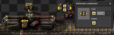
=== Memory Cell Design === | === Memory Cell Design === | ||
*This circuit counts the number of items of each type on a looping belt by counting the numbers that are added and removed from the belt by inserters. | * This circuit counts the number of items of each type on a looping belt by counting the numbers that are added and removed from the belt by inserters. | ||
*Each inserter that takes items off the belt is connected together with Red wire and each of these inserters is set to '''Mode of operation none, Read hand content selected''' and '''Hand read mode pulse'''. | * Each inserter that takes items off the belt is connected together with Red wire and each of these inserters is set to '''Mode of operation none, Read hand content selected''' and '''Hand read mode pulse'''. | ||
*These inserters are connected to the input of the left arithmetic combinator. | * These inserters are connected to the input of the left arithmetic combinator. | ||
*The left [[Arithmetic combinator]] multiples '''each''' input by '''-1''' and outputs it to '''each'''. | * The left [[Arithmetic combinator]] multiples '''each''' input by '''-1''' and outputs it to '''each'''. | ||
*The right [[Arithmetic combinator]] is a '''memory cell''' as above. | * The right [[Arithmetic combinator]] is a '''memory cell''' as above. | ||
*The memory cell's input is connected to the inserters that are placing items on the belt and the output of the left [[Arithmetic combinator]]. | * The memory cell's input is connected to the inserters that are placing items on the belt and the output of the left [[Arithmetic combinator]]. | ||
*The inserters that place items onto the belt have an enabled condition that is based on the number of items on the belt. | * The inserters that place items onto the belt have an enabled condition that is based on the number of items on the belt. | ||
{{clear}} | {{clear}} | ||
== Splitters == | == Splitters == | ||
[[file:CondSplitter.png|left]] | [[file:CondSplitter.png|left|400x400px]] | ||
=== Conditional splitter === | === Conditional splitter === | ||
*This is the most simple circuit you can have for "controlling" a splitter. | * This is the most simple circuit you can have for "controlling" a splitter. | ||
*A signal X=1 is transmitted from off screen when the items need to be sent down the belt. | * A signal X=1 is transmitted from off screen when the items need to be sent down the belt. | ||
*The belt on the left is enabled when X=1. | * The belt on the left is enabled when X=1. | ||
*The belt on the right is enabled when X=0. | * The belt on the right is enabled when X=0. | ||
*The two belts are wired together and to a pole. | * The two belts are wired together and to a pole. | ||
{{clear}} | {{clear}} | ||
[[File:PrioritySplitter.png|left]] | [[File:PrioritySplitter.png|left|400x400px]] | ||
=== Priority Splitter === | === Priority Splitter === | ||
*This circuit | * This circuit prioritizes items to the belt going of the screen to the left but will send items straight on if the belt to the left is backed up. | ||
*Its not perfect and will leak some items but its good enough for most applications. | * Its not perfect and will leak some items but its good enough for most applications. | ||
*The balancer means it will work even if the supply or demand is uneven. | * The balancer means it will work even if the supply or demand is uneven. | ||
<br /> | <br /> | ||
*It is critical that the belts are setup as in this picture otherwise it may not work. | * It is critical that the belts are setup as in this picture otherwise it may not work. | ||
{{clear}} | {{clear}} | ||
== Power == | == Power == | ||
[[File:SteamBackup.png|left]] | [[File:SteamBackup.png|left|400x400px]] | ||
=== Backup steam power === | === Backup steam power === | ||
*The [[steam engine]]s are not directly connected to the power network. They are connected to the power network through a [[Power switch]]. | * The [[steam engine]]s are not directly connected to the power network. They are connected to the power network through a [[Power switch]]. | ||
*The [[power switch]] is connected to one of the [[accumulator]]s in the main network. | * The [[power switch]] is connected to one of the [[accumulator]]s in the main network. | ||
*The [[power switch]] turns on when A < 10. That is when the [[accumulator]]s are less than 10% full. | * The [[power switch]] turns on when A < 10. That is when the [[accumulator]]s are less than 10% full. | ||
{{clear}} | {{clear}} | ||
== Latches == | == Latches == | ||
[[File:SRLatch.png|left]] | [[File:SRLatch.png|left|400x400px]] | ||
=== SR latch === | === SR latch === | ||
*This should be familiar to anyone with any background in electronics. | * This should be familiar to anyone with any background in electronics. | ||
*The signal is set and reset with the [[constant combinator]]s on the left by setting an A=1 signal. | * The signal is set and reset with the [[constant combinator]]s on the left by setting an A=1 signal. | ||
*The latch "remembers" which one was last set and the light stays on until another signal is received. | * The latch "remembers" which one was last set and the light stays on until another signal is received. | ||
{{clear}} | {{clear}} | ||
[[File:SRlatchinaction.png|left]] | [[File:SRlatchinaction.png|left|400x400px]] | ||
=== Usage of SR latch === | === Usage of SR latch === | ||
*Here is an example of how you could use an SR latch. | * Here is an example of how you could use an SR latch. | ||
*The two extra [[Decider combinator]]s provide the set and reset conditions. | * The two extra [[Decider combinator]]s provide the set and reset conditions. | ||
*Petroleum gas < 50 and petroleum gas > 100. | * Petroleum gas < 50 and petroleum gas > 100. | ||
{{clear}} | {{clear}} | ||
[[File:BeltLatch.png|left]] | [[File:BeltLatch.png|left|400x400px]] | ||
=== Belt only latch === | === Belt only latch === | ||
*This is the most compact latch I am aware of. | * This is the most compact latch I am aware of. | ||
*To make it work you need to place '''3''' raw wood on the inside lane of the belt. | * To make it work you need to place '''3''' raw wood on the inside lane of the belt. | ||
*I believe it will have higher latency than the combinator version but in most situations you will not notice the difference. | * I believe it will have higher latency than the combinator version but in most situations you will not notice the difference. | ||
{{clear}} | {{clear}} | ||
== Displays == | == Displays == | ||
[[File:5digitDisplay.png|left]] | [[File:5digitDisplay.png|left|400x400px]] | ||
=== Numerical Display === | === Numerical Display === | ||
*Each digit is driven by its own [[Green wire]], that wire holds 15 signals one for each lamp used in the digit. | * Each digit is driven by its own [[Green wire]], that wire holds 15 signals one for each lamp used in the digit. | ||
*[[Constant combinator]]s are used to define which lamp should light up for each value. | * [[Constant combinator]]s are used to define which lamp should light up for each value. | ||
*Blueprint string | * Blueprint string including decoder [https://www.dropbox.com/s/5o13xuwthalzzfe/Brain2.txt?dl=0] | ||
{{clear}} | {{clear}} | ||
[[File:BWDisplay.png|left]] | [[File:BWDisplay.png|left|400x400px]] | ||
=== Black and White Grid Display === | === Black and White Grid Display === | ||
*Each row has its own [[Red wire]] connection and within that row each light has a numbered signal 0-9. | * Each row has its own [[Red wire]] connection and within that row each light has a numbered signal 0-9. | ||
*We turn each light on by just setting or clearing the relevant signal. | * We turn each light on by just setting or clearing the relevant signal. | ||
{{clear}} | {{clear}} | ||
[[File:MultiColoredDisplay.png|left]] | [[File:MultiColoredDisplay.png|left|400x400px]] | ||
=== Multicolor Display by DaveMcW === | === Multicolor Display by DaveMcW === | ||
*To understand how this works, you first need to understand how color lights choose which color to light up when there are multiple colored signals. | * To understand how this works, you first need to understand how color lights choose which color to light up when there are multiple colored signals. | ||
*The [[lamp]] will light up with the colored signal that is greater than zero and earliest in this list: Red, Green, Blue, Yellow, Pink, Cyan, White. | * The [[lamp]] will light up with the colored signal that is greater than zero and earliest in this list: Red, Green, Blue, Yellow, Pink, Cyan, White. | ||
*We have a [[Red wire]] per column, that wire has each of the colored signals on it at different values and a numbered signal for each row. | * We have a [[Red wire]] per column, that wire has each of the colored signals on it at different values and a numbered signal for each row. | ||
*There is a [[Arithmetic combinator]] for each cell that subtracts the "row" value from each of the colored signals. | * There is a [[Arithmetic combinator]] for each cell that subtracts the "row" value from each of the colored signals. | ||
*And this enables us to choose the color for each cell. | * And this enables us to choose the color for each cell. | ||
*Simple! | * Simple! | ||
{{clear}} | {{clear}} | ||
== See Also == | == See Also == | ||
*[[Arithmetic combinator]] | * [[Arithmetic combinator]] | ||
*[[Constant Combinator]] | * [[Constant Combinator]] | ||
*[[Decider Combinator]] | * [[Decider Combinator]] | ||
*[[Circuit network]] | * [[Circuit network]] | ||
Revision as of 00:09, 2 December 2016
Introduction
This page provides examples of simple circuit network designs and some not so simple designs that others can use, combine and modify. They are designed to be as easy to understand as possible.
Oil Setups

Light Oil Cracking
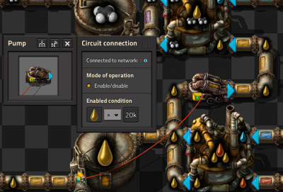
- This circuit provides balanced light oil and petroleum gas production by cracking excess light oil into gas.
- The Small pump is connected to the Storage tank by a Red wire.
- The small pump has an enabled condition set to Light Oil > 2000.

Heavy Oil Cracking
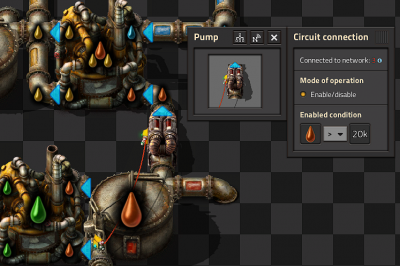
- This circuit extends on the previous circuit by adding optional heavy oil cracking to provide lubricant etc.
- The Small pump has an enabled condition set to Heavy oil > 2000.

Petroleum split evenly between plastic and sulphuric acid
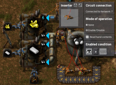
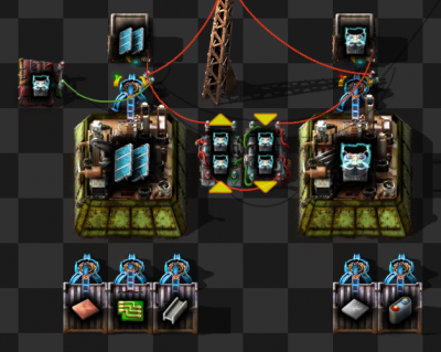
- This circuit buffers gas in the tank until there is at least 100, then it lets the tank drain until there is less than 50 and the cycle repeats.
- It has a few elements that work together to do achieve this.
- Firstly the Small pump is connected to the Wooden chest by a Red wire and the enabled condition on the Small pump is set to Raw wood > 0.
- Both of the Basic inserters are connected to the Storage tank by Red wires.
- The enabled condition on the left inserter is Petroleum gas > 100
- The enabled condition on the right inserter is Petroleum gas < 50.
- You will need to insert a single "Raw wood" into the chest to make it all work.
- It is also possible to do this with decider combinators instead of the inserters, belt and the Wood chest or even just belts.
Lights

Conditional Lights
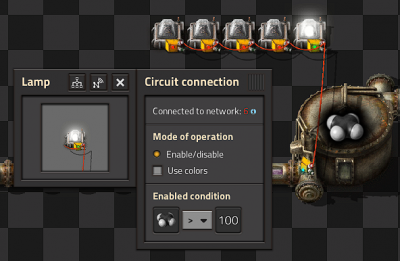
- In this circuit we connect a series of lamps to a Storage Tank.
- By setting different conditions on each lamp we can build an indicator strip.
- The Enabled condition of the first lamp is Petroleum gas > 100.
- The others light up when gas is greater than 200, 300, 400 and 500 respectively.

Colored Lights
- To light a lamp with a color rather than white, you need to do two things.
- 1. Send a colored signal to the lamp
- 2. Select the "Use colors" check box on the lamp.
- In this case we want to convert a Petroleum gas signal into a pink signal.
- We can do this with an Arithmetic combinator, setting the input to Petroleum Gas + 0 (the constant 0 not the signal 0) and set the output to the Pink signal (on the bottom row of the last tab of signals.)
Misc

Multiple Storages
- If you connect multiple chests to a pole, the pole displays the sum of items in all the chests.
- This also works with Storage tanks and roboports.

Constant combinator
- With a constant combinator you can generate any signals you my need.
- In this example we have generated a signal of 50 Laser turrets and 200 Piercing round magazine.
- Constant combinators are not of much use on their own but we shall use them later.

Logic gates
- In each case the two inputs can be connected with the same color wire or different colors. The inputs are powered by two Constant combinators each of them output an A signal with value 1 for true and nothing or false.
- You can use Decider combinators to make all of the common logic gates.
- The output for each should be set to 1 and the signal of your choice.
- Use the following settings to create different gates:
   NOT  A=0
   NOR  A=0
   NAND A<2
   XOR  A=1
   AND  A=2
   OR   A>0

Constant combinator signs
- You can use Constant combinators to make signs, just set the letter signals in the combinator, each combinator can display 2 characters side by side.

Memory Cell / Counter
- Basic memory cell that counts all the items moved by the inserter
- The Fast inserter is connected to BOTH ends of the arithmetic combinator.
- If the Fast inserter hasn't picked anything up this tick the input to the Arithmetic combinator is the same as and output and hence the values are persisted.
- When the Fast inserter does pick something up its value is added to the output from the previous tick thus incrementing that item.
Inserters

Limit items placed into a chest
- The Basic inserter is connected to the Wooden chest using a Red wire.
- The inserter's enabled condition is Advanced Circuit < 10.
- In reality this means the inserter may place more than 10 Advanced circuits in the chest because it could pick up-to 3 at once.
- This effect can be even greater with Stack inserters because of their large carrying capacity.
- This technique still gives far greater control than limiting the inventory on the chest.

Keeping outpost stocked with specified items
- This circuit keeps a Storage chest at an outpost stocked with customized levels of different items.
- For example you could keep an outpost stocked with 50 laser turrets and 200 piercing magazine rounds but not have to worry about it being over filled.
- The storage chest is attached to the input of the Arithmetic combinator (left side in the picture) with a Red wire.
- Another couple of Red wires join the output of the Arithmetic combinator (right side) to the constant combinator and to the stack filter inserter.
- The Arithmetic combinator multiples each input value (from the storage chest) by -1.
- Finally the filter stack inserter's mode of operation is set to Set filters.
- So the input to the stack filter inserter is <Constant combinator> - <Storage chest contents> and the filter is set to filter the item of greatest demand.

Balanced Solar panel / Accumulator Production
- This circuit balances production of Solar panels and Accumulators to a desired ratio in my case 24:20.
- The first Arithmetic combinator takes the number of accumulators in the chest and multiples it by 24.
- The second Arithmetic combinator takes the output of the first combinator and divides it by 20.
- This gives us the number of accumulators that we can directly compare to the number of Solar panels in both inserters.
- If the number of accumulators is greater we enable the Solar panels inserter, if the number of Solar panels is greater we enable the accumulators inserter.
- However, if they are equal neither machine does anything. So we add a single accumulator to one of the inserters using a constant combinator and a wire of the other color thus breaking the deadlock.
Sushi Belts

Reading Belt Design
- Six belts in a row are connected with Red wire and set to Read belts contents and Hold
- This Red wire is then connected to the inserters that insert onto the belt.
- Read hand contents is unselected for all inserters.
- Mode of operation is set to Enable/Disable on all inserters.
- The first inserter is enabled when Science pack 1 = 0
- The other inserters are set similarly for the other science packs.
![left]](/File:SushiScience2.png)
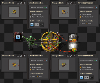
Memory Cell Design
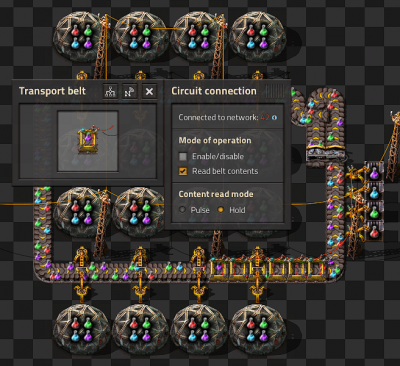
- This circuit counts the number of items of each type on a looping belt by counting the numbers that are added and removed from the belt by inserters.
- Each inserter that takes items off the belt is connected together with Red wire and each of these inserters is set to Mode of operation none, Read hand content selected and Hand read mode pulse.
- These inserters are connected to the input of the left arithmetic combinator.
- The left Arithmetic combinator multiples each input by -1 and outputs it to each.
- The right Arithmetic combinator is a memory cell as above.
- The memory cell's input is connected to the inserters that are placing items on the belt and the output of the left Arithmetic combinator.
- The inserters that place items onto the belt have an enabled condition that is based on the number of items on the belt.
Splitters

Conditional splitter
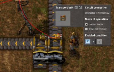
- This is the most simple circuit you can have for "controlling" a splitter.
- A signal X=1 is transmitted from off screen when the items need to be sent down the belt.
- The belt on the left is enabled when X=1.
- The belt on the right is enabled when X=0.
- The two belts are wired together and to a pole.

Priority Splitter
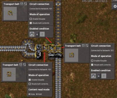
- This circuit prioritizes items to the belt going of the screen to the left but will send items straight on if the belt to the left is backed up.
- Its not perfect and will leak some items but its good enough for most applications.
- The balancer means it will work even if the supply or demand is uneven.
- It is critical that the belts are setup as in this picture otherwise it may not work.
Power

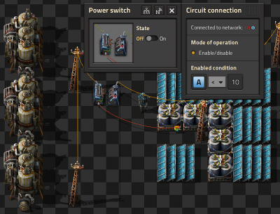
Backup steam power
- The steam engines are not directly connected to the power network. They are connected to the power network through a Power switch.
- The power switch is connected to one of the accumulators in the main network.
- The power switch turns on when A < 10. That is when the accumulators are less than 10% full.
Latches

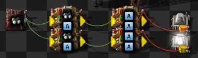
SR latch
- This should be familiar to anyone with any background in electronics.
- The signal is set and reset with the constant combinators on the left by setting an A=1 signal.
- The latch "remembers" which one was last set and the light stays on until another signal is received.

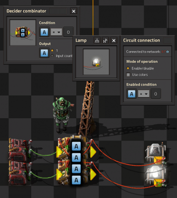
Usage of SR latch
- Here is an example of how you could use an SR latch.
- The two extra Decider combinators provide the set and reset conditions.
- Petroleum gas < 50 and petroleum gas > 100.

Belt only latch
- This is the most compact latch I am aware of.
- To make it work you need to place 3 raw wood on the inside lane of the belt.
- I believe it will have higher latency than the combinator version but in most situations you will not notice the difference.
Displays

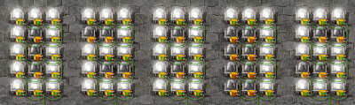
Numerical Display
- Each digit is driven by its own Green wire, that wire holds 15 signals one for each lamp used in the digit.
- Constant combinators are used to define which lamp should light up for each value.
- Blueprint string including decoder [1]

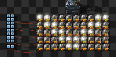
Black and White Grid Display
- Each row has its own Red wire connection and within that row each light has a numbered signal 0-9.
- We turn each light on by just setting or clearing the relevant signal.

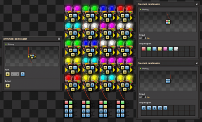
Multicolor Display by DaveMcW
- To understand how this works, you first need to understand how color lights choose which color to light up when there are multiple colored signals.
- The lamp will light up with the colored signal that is greater than zero and earliest in this list: Red, Green, Blue, Yellow, Pink, Cyan, White.
- We have a Red wire per column, that wire has each of the colored signals on it at different values and a numbered signal for each row.
- There is a Arithmetic combinator for each cell that subtracts the "row" value from each of the colored signals.
- And this enables us to choose the color for each cell.
- Simple!